Space Shuttle Launch Complex 39-B Construction Photos
Page 36
STS-2 on Pad A, RSS Supported by Falsework
(Original Scan)
Top Left: STS-2 rolled out and sitting on Pad 39-A
All others: RSS still sitting on falsework.
When I first arrived at the pad, there was no RSS, and Wilhoit (who was the steel erector for the steel that Sheffield had fabricated) had only put up a single line of falsework. A total of five lines were put up and the first major thing that happened next was the setting of the
RSS 135' level Bottom Truss upon it. The centerline for that iron was actually at elevation 134'-2" but since it was 24" Ø pipe, half of of that equals a foot, and you add that foot to 134' and you get 135' for your T.O.S. (Top Of Steel) and 135' is what everybody called it, so that's what we're going with, ok?
Imagine an enormous cats-cradle of steel, over one hundred and fifty feet long, mostly made of 24-inch diameter structural pipe weighing up to 374 pounds per linear foot, but with some both larger and smaller diameter pipe, and some heavy wide-flange beams, being lifted by a pair of cranes, until it was suspended above the falsework. Then imagine both cranes, in synchrony, letting this cycloptic pipe truss down onto the five falsework frames. Pretty radical, right? But it gets even more radical. On each falsework frame was an ironworker with a come-along and a bit of rigging, which was tied to that bottom line of structural pipe which was now resting, on edge, across all five falsework frames, steadied from above by the two cranes, still hooked to the truss. And then, using nothing more than those five ironworkers with come-alongs, they started dragging that bottom line of pipe across the falsework, toward the rear of where the RSS would soon appear, and as the cranes let out on their lines with exquisite slowness, they come-alonged that damned truss all the way across the falsework and by the time they'd gotten it to the far side, the cranes had let down to the point where the top of the truss was now resting as pretty as you please, right where the bottom of the truss had been a few hours before. Cut it all loose, get the cranes out of the way, and thank you very much, you now have yourself an RSS Bottom Truss right where it belongs. Five guys and two cranes. To this day I marvel at the simplicity, economy, and elegance of it all.
It was astounding.
Additional commentary below the image.
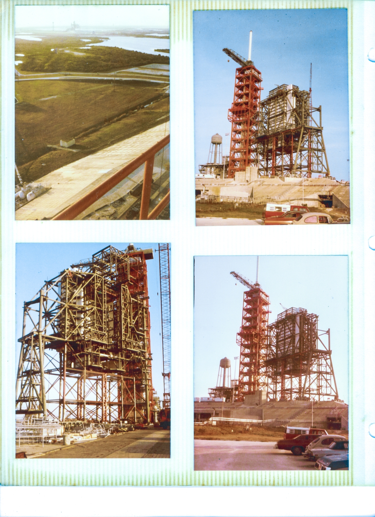
Top Left: (Full-size)
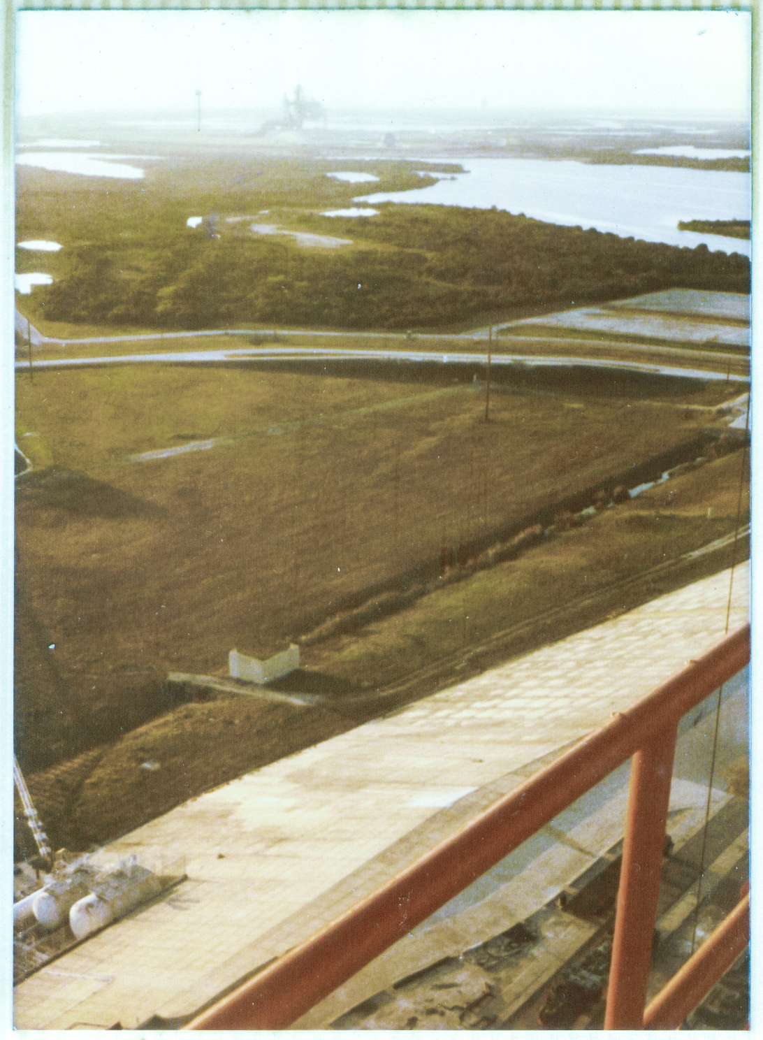
Another shot of STS-2 on the pad, over at A-Pad.
This is pretty much the exact same shot as the one on the previous page, except that I've rotated the camera around to where the long axis of the frame is vertical, instead of horizontal, in order to include a bit more down on the ground below me.
There's not a whole lot going on down there, nor much to make note of, with perhaps one exception.
Look close at the image, down near the bottom-left corner of the frame, and you can make out some white tanks, sitting in a bit of a cutout at the bottom of the sloping edge of the pad.
This is part of the pad's high-pressure gas equipment (there is more of it, just out of frame, in a much larger cutout) and what you're seeing is left over from Apollo days, and eventually we were tasked with removing it (when I worked for Ivey, as opposed to Sheffield, who I was working for when these shots were taken).
Ok, so what?
Well, when time came to get a crane and lift those tanks out of there and put them on something to haul them off, it turned out that of the three tanks you can see (the third one is almost completely obscured the the lower of the two larger ones, is much smaller in diameter, and is bit longer, too, and extends out of the image frame on the its left margin), that third one was a bastard. It was heavy. Heavier than both of the other, larger, tanks put together, in fact. I do not remember what sort of pressure it was rated for, but whatever it was, it was definitely high pressure. If memory serves, that thing had a four inch wall thickness on it! 4 inches of steel! It was built like a battleship. Heavy motherfucker. But we got it out of there alright, so in the end, all was well.
But did I mention that it was heavy? No? Very well then, it was heavy.
Top Right: (Full-size)
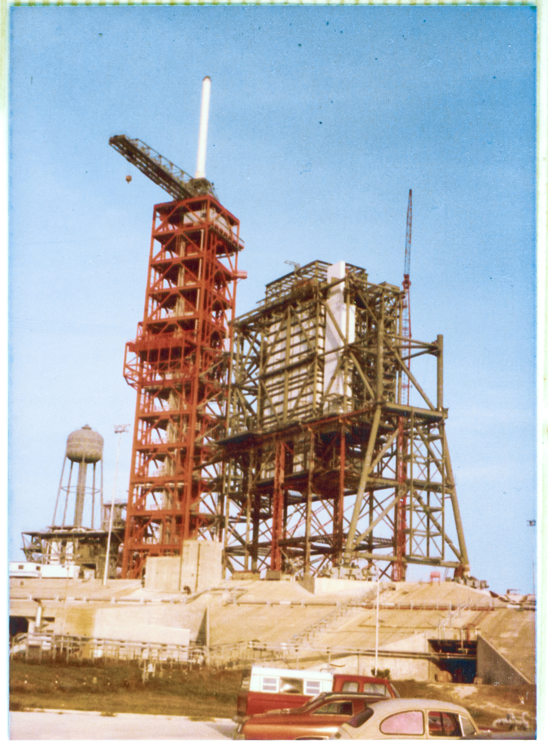
Sheffield Steel days, Wilhoit still erecting the RSS.
Before the falsework was removed.
When the FSS was still red.
Look close, at the enlarged image, and you can see one of the main reasons that the falsework is still in place, still supporting the RSS.
To the right of the image, you can see (With, again, utmost thanks to Manfred Rohr in Germany, for providing me with the link to download these structural demolition plans for Pad B, and, while we're at it here, if anybody has a set of the original fabrication and erection drawings, please let me know, so I can incorporate them into these photo essays.) the Column Line 7 main-framing reaching from the pad deck, into the sky.
Despite what a quick glance at that drawing might give you to believe, Column Line 7 only extended vertically to elevation 171'-2" and did not continue on to elevation 208'-2" which was the elevation of the top truss of the RSS.
From 171' up, the main-framing members on Column Line 7 slanted diagonally over to Column Line 6, which was where they met the rest of the heavy iron up at the 208' elevation.
A look at the framing on Column Line A (the "back" side of the RSS, which is closest to you in the image), will show you what I mean.
Ditto Column Line B.
So ok, so back to the image. Look close, and you can see that all three main framing members running diagonally from line 7 to line 6, between elevations 171' and 208' are not there.
So yeah, they weren't yet ready to cut the RSS loose and let it stand on its own, unsupported by anything else, not quite just yet.
And now that we're talking about the main-framing in regards to very heavy pipes that run up-and-down, side-to-side, and diagonally, let's talk about the places where all those pipes had to come together. Where all those pipes had to be cut, fit, and full-penetration welded from one to another.
We've talked about this before, and now we're going to talk about it again. This stuff is beyond belief and yet here it sits, calmly supporting a tremendous set of loads, both static and dynamic.
Maybe get a look at the stub cluster on Column Line A, up at elevation 171', where it meets Column Line 2 as an example. Look closely at all three of the drawings for this area (and it takes all three to fully show this stub cluster), and make note of the very small "dash" mark running perpendicularly through the line of the pipe, which is rendered right next to the center of the cluster, on each pipe. These "dashes" are noted on all three drawings as "FIELD SPLICE" and each "dash" represents where one pipe gets welded, in the field, up in the air, by one of Wilhoit's ironworkers, to its mating piece.
And what about the guys in Sheffield's fabrication shop? What about those guys, too?
Early 1980's. No computers. This stuff all had to be worked out with pencil and paper. Angles, thicknesses, diameters, centerlines, camber, deflections, sequence of assembly, and god knows what else, by hand!
Go back and look at that thing again, dammit.
I see the following differing kinds of pipes:
18"Ø x 59, 18"Ø x 71, 18"Ø x 93, 18"Ø x 116, 18"Ø x 138, 22"Ø x 72, 22"Ø x 157.
No two alike in working diameters or wall thicknesses.
Coming into each other all in the same place at a bewildering array of differing directions and angles.
And we're talking heavy iron here.
Maybe go get a few cardboard inserts for paper-towel rolls. Can't need more than a couple of dozen of 'em right? That way you'll have some spares.
You'll be needing those spares.
Now go get your exacto knife, or, if you're feeling adventurous, just a pair or scissors, and then cut curves into the ends of those sonofabitches so as they all come exactly together, no gaps, no interference, centerline-dead-into-centerline, every angle on every diagonal dead-fucking-nuts, for every last one of those bastards. Before you start cutting, be sure and calculate the angles for the diagonals using the dimensions between stub clusters as given on the drawings. Correctly, please. Determine which pipe gets cut away to accommodate which other pipe, too. Correctly, I might add. And then, when you're done doing that, be sure and calculate the sequence of assembly, from first pipe to last, too. And yeah, you gotta do that one correctly as well.
Did you have enough paper-towel rolls?
Or did you fuck 'em all up, and wind up throwing the whole goddamned mess away in frustration?
Yeah.
Now go getcha some nice heavy iron. Weighing up to 157 pounds per running foot in this particular instance, and do it using that.
Yeah.
I thought so.
Now go back and look at that image.
And maybe think about what's going on where those fucking pipes are all coming together.
And I would walk out of the Sheffield Steel field trailer, and this would be staring me right in the face, and I would stand there in the late afternoon, maybe just before getting into my little yellow VW Bug, just before winding around through the lengthening shadows to the Beach Road and the drive home past all the other launch pads on Kennedy Space Center and Cape Canaveral, and consider stuff like this, and occasionally a shiver would run down my spine as the sheer magnitude and intensity of what was arrayed all there before me, set in.
The people who did this sort of thing were walking and working, all around me.
And they didn't look a bit special, or otherwise worthy of the least additional interest above and beyond what you might give to any other assemblage of strangers and acquaintances.
But they were different.
And, I suppose, slowly, ever so slowly and creepingly, I was becoming different, too.
I dunno. I try to explain. People always ask me "What was it like?" People want to know how it felt. People want to know what was going on from a personal point of view. From the standpoint of one of the participants.
And so I try to answer them. I try to answer them as honestly as I can.
I try to tell them what it was like.
But I don't think I'm doing a very good job of it.
I do not know.
Bottom Left: (Full-size)
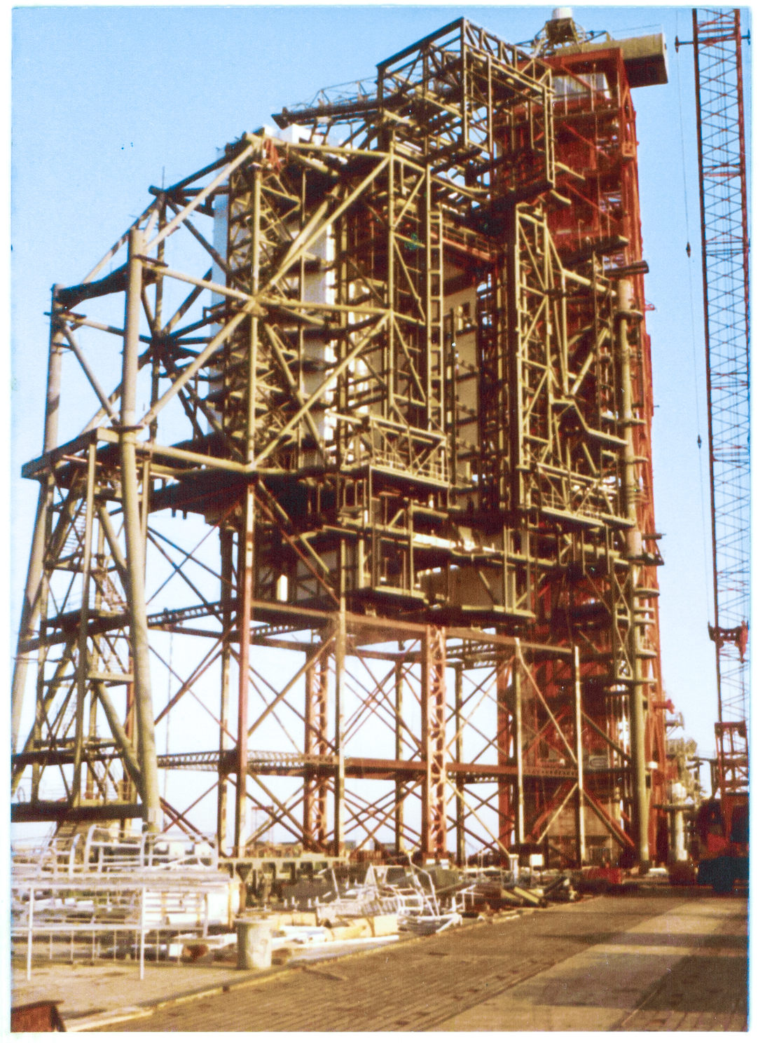
It's early morning, and you're up on the pad deck, right around where the south end of the flame trench intersects the pad slope, and it looks like a load of caged ladders, and other miscellaneous metals has been placed in this part of the shakeout yard, awaiting perhaps an inventorying by yourself, or others, or perhaps that's done and they're due to be picked up by the crane and hung on the tower fairly soon.
We cannot know, just by looking at this image.
Looming above it all, the RSS stands atop its falsework, cyclopean, enigmatic, otherworldly, speaking clearly to you in a language that you do not understand.
The last of the main-framing between Column Lines 6 and 7, between 171' and 208' has been installed, but the falsework still remains in place beneath it all.
The stub clusters described in the paragraphs just above can be seen in several places, and the one on Line A / Line 6 at elevation 171', plainly visible with blue sky behind it all around, in particular looks quite formidable. I count a total of 11 separate main-framing heavy structural members, radiating from it in all directions.
I cannot even sensibly imagine the complexities of bare-handed, pencil-and-paper, torch-kit and welding-machine, calculating, cutting, fitting, and welding that thing together in the fabrication shop, and then finishing it off, working from floats, in the field. It is beyond me. It is more than I can fathom.
Bottom Right: (Full-size)
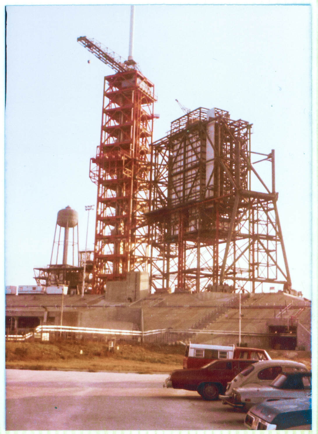
And one more shot from out in front of the field trailer, with the Line 7, 171' to 208' main framing steel missing, in early-morning light.
In the bottom right corner of the frame, just above my little yellow VW Beetle, the dark rectangle of the mouth of the tunnel that ran through the pad from one side to the other, can be seen.
Deep inside this tunnel, you would gain access to both sets of catacombs, east and west.
Return to 16streets.comACRONYMS LOOK-UP PAGEMaybe try to email me? |